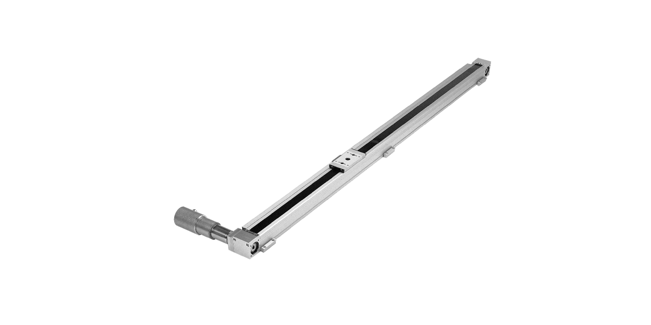
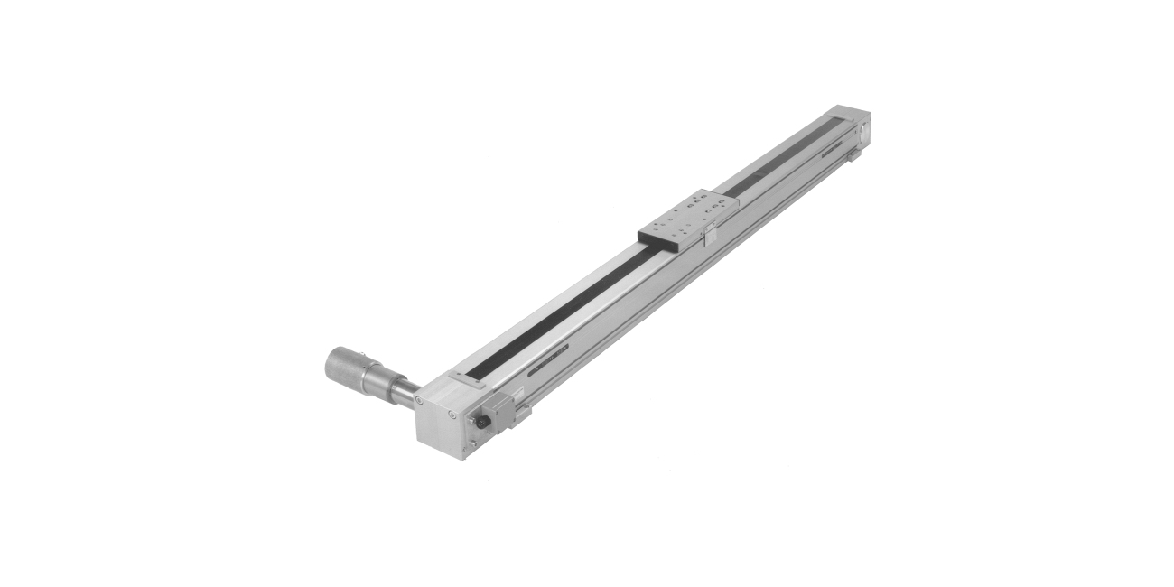
System information

Function

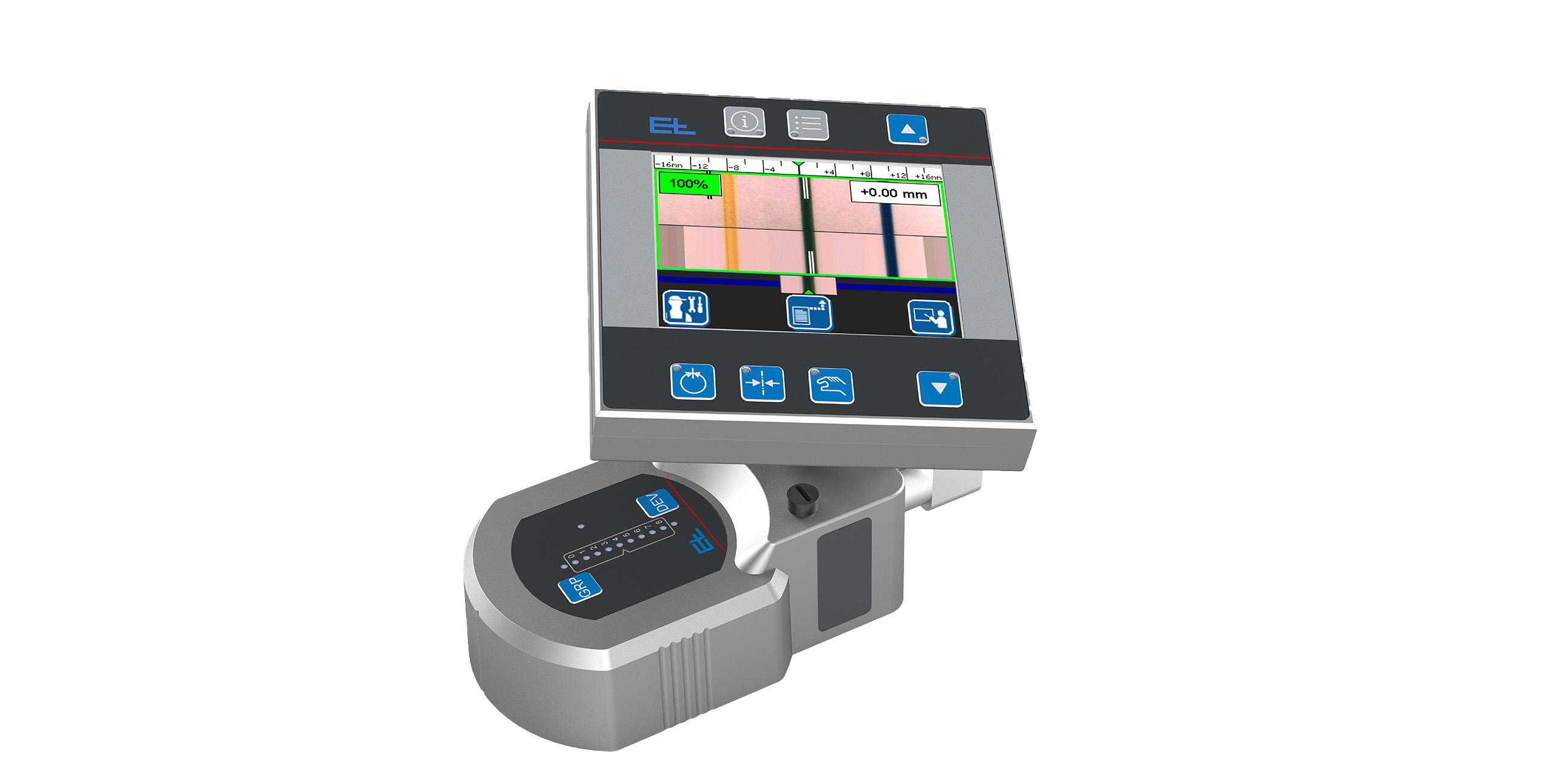
With follow-up control, the sensor and tool are mounted jointly on a linear guide. Here, the sensor detects the position of the web and thus determines the actual position value of the tool.

This is compared with the target value and is output to the actuator as a correction signal. Through position control or follow-up control, the tool is always followed up with a constant distance to the guide reference.

Area of use

Follow-up controllers are used when processes such as coating or cutting must be executed with a constant distance to the web edge or a guide reference on the web.

Application

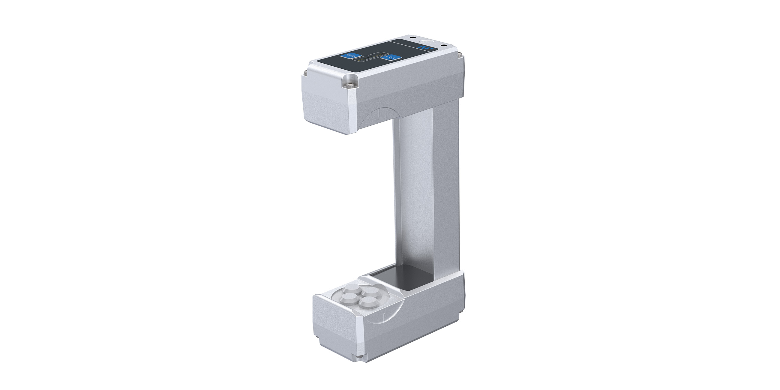
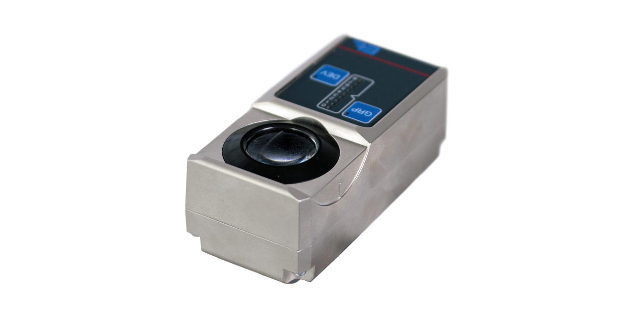
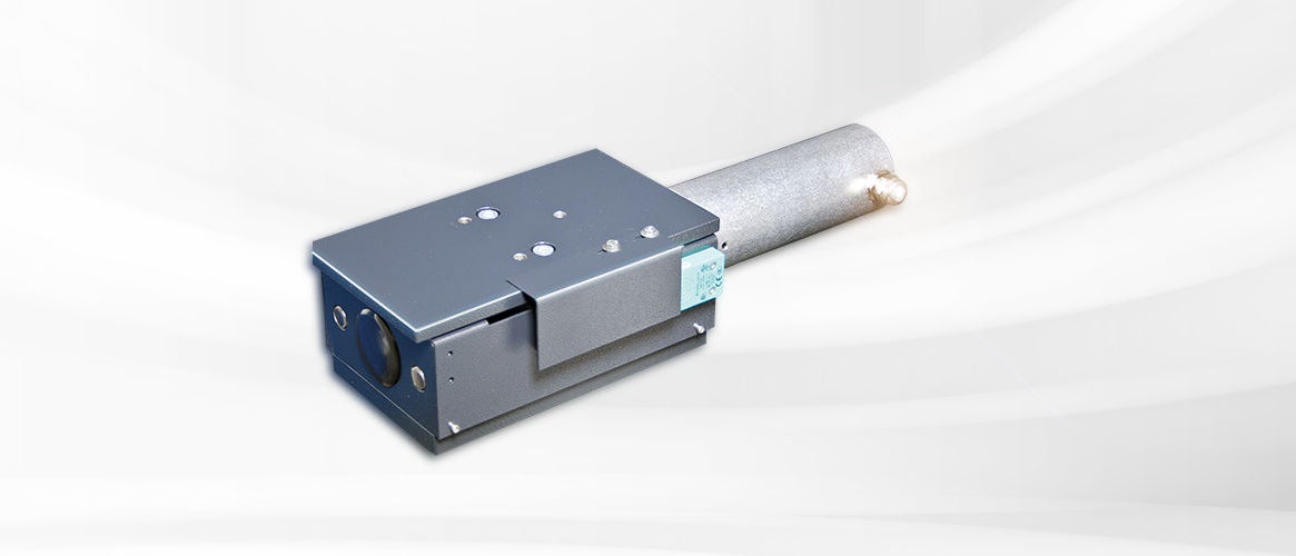
The highest accuracy in position control is reached when the sensor and tool (doctor blade limitation) can be assembled in compact form on a linear unit. Edge detection always takes place in front of the tool, in the direction of web travel.

ELPOSER

Legend

1 = Doctor blade edge limit | 2 = Doctor blade | 3 = Linear unit | 4 = Edge sensor | AB = Operating width | L1 = Distance between web edge and coating

Web guiding systems

Linearführungssystem VGB14

Lineares Positionier- und Nachlaufsystem für Spachteln, Saugdüsen, Schneidgeräte, Markiergeräte und Randabheber, ausgelegt für eine Nenntraglast von 1.000 N

More info

Linearführungssystem VSB50

Lineares Positionier- und Nachlaufsystem für Spachteln, Saugdüsen, Schneidgeräte, Markiergeräte und Randabheber, ausgelegt für eine Nenntraglast von 250 N

More info

Linearführungssystem VSB60

Lineares Positionier- und Nachlaufsystem für Spachteln, Saugdüsen, Schneidgeräte, Markiergeräte und Randabheber, ausgelegt für eine Nenntraglast von 500 N

More info

System components

Ultraschall-Kantensensor PoE FX 42

Ultraschall-Kantensensor mit digitaler Auswertung, Sichtbereich von ±3 mm und Gabelweiten von 30, 60 und 124 mm

More info

Ultraschall-Kantensensor PoE FX 52

Ultraschall-Kantensensor mit digitaler Auswertung, Sichtbereich ±10 mm und Gabelweiten von 30, 60 und 124 mm

More info

Infrarot-Kantensensor PoE FR 54

Infrarot-Kantensensor nach Prinzip der Retroreflexion mit einem Messbereich von ±10 mm und einer Auflösung von 0,02 mm

More info

Infrarot-Breitbandsensor PoE FR 61

Infrarot-Breitbandsensor mit großem Messbereich von 160 mm, 320 mm oder 480 mm

More info

Blue light-Breitbandsensor PoE FR 65

Blue-Light-Durchlichtsensor mit großem Messbereich von 160 / 320 und 480 mm

More info

Farblininensensor FE 52

Digitaler Farbmatrixsensor zur Erfassung von Farblinien und Farbkontrasten

More info

Bediengerät DO 42

Visualisierung und Bedienung von Bahnlaufregelsystemen mit Mehrfachbedienung von bis zu 255 Bahnlaufregelkreisen

More info

Daten-Netzwerkzentrale DN 40

Daten-Netzwerkzentrale zum zentralen Anschluss aller Komponenten in einem Regelsystem

More info

Contact

Write to us! We are looking forward to your message.

Salutation
*Required field