System information

Function

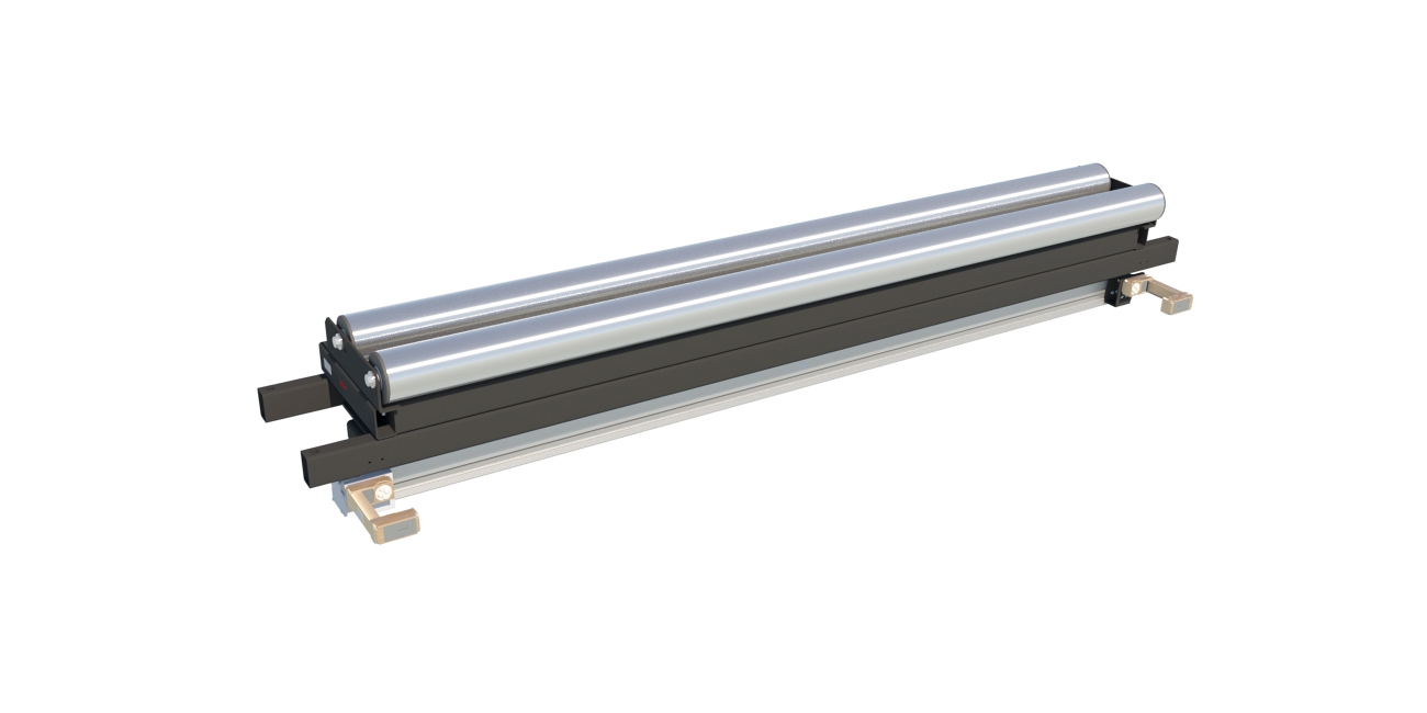
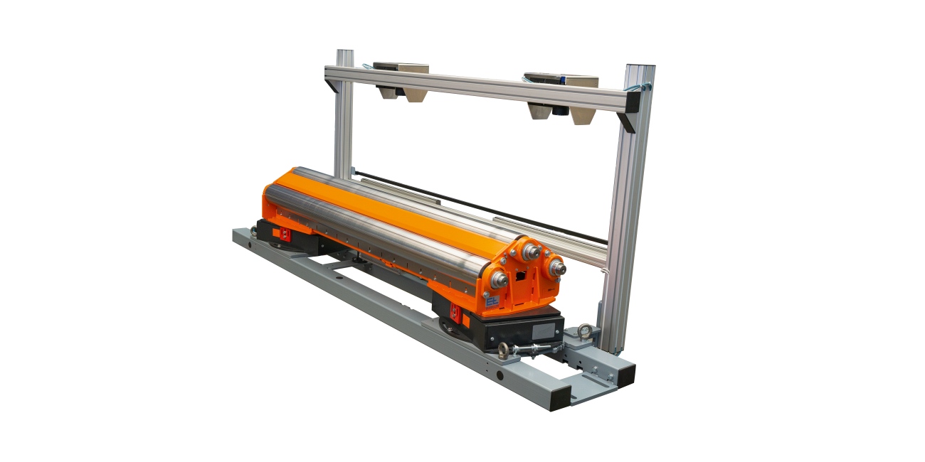
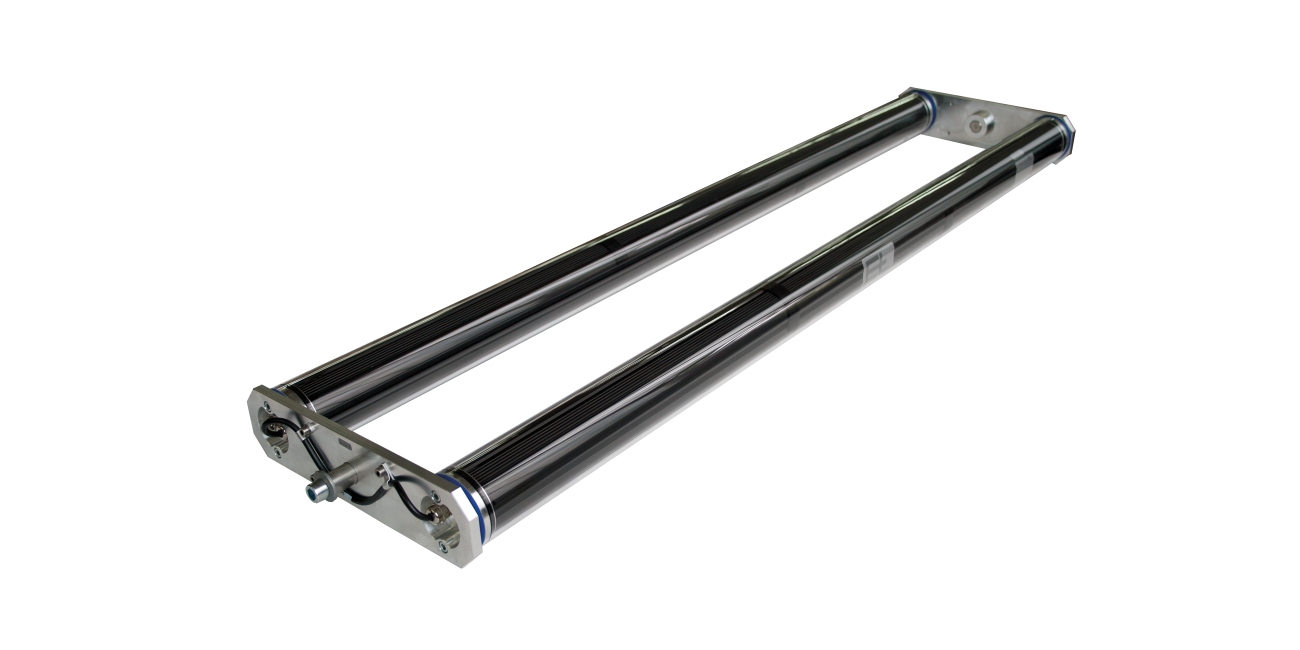
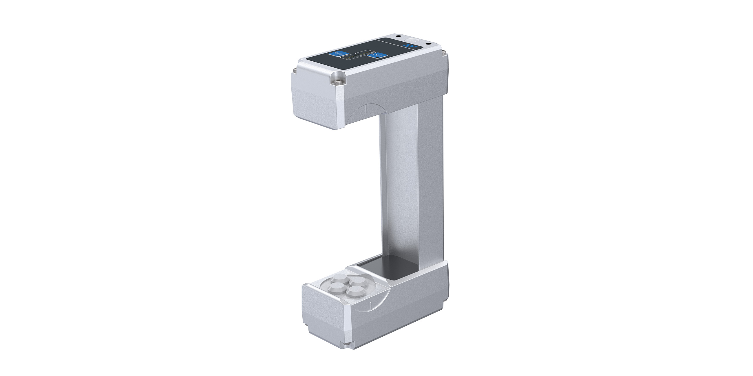
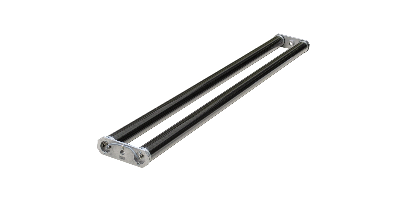
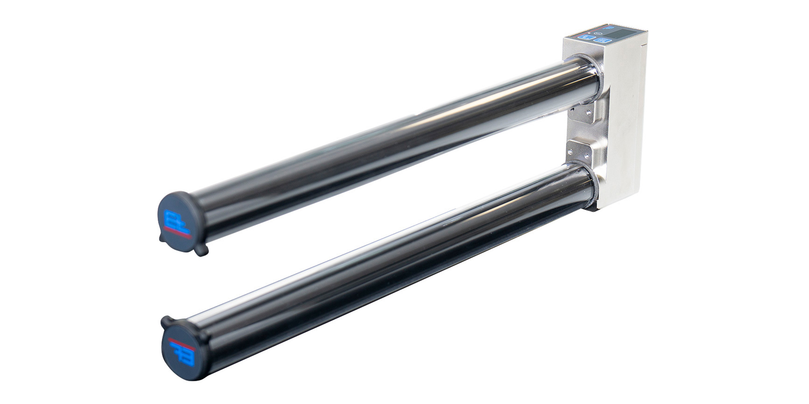
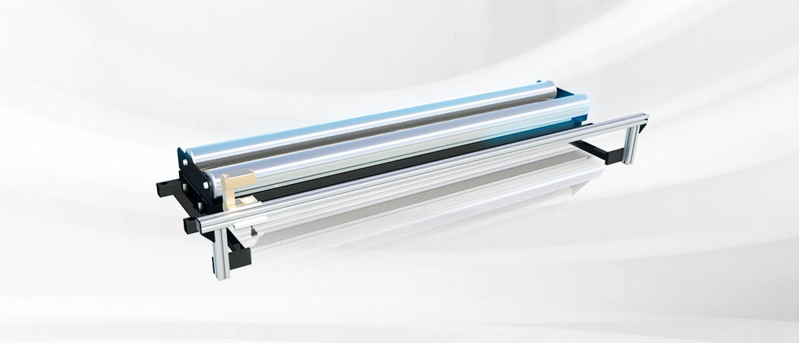
ELROLLER steering roller systems used for web guiding already correct the web position on the infeed plane. They consist of a fixed base frame and a movable guide frame. The latter accommodates one or two positioning rollers and swivels around an imaginary pivot point on the infeed plane. A steering roller is referred to as a proportional actuator, which means that it operates under friction and must not permit slipping between the web and positioning roller.

Area of use

ELROLLER systems are always used for web guiding where there is a long entry path due to technical process reasons.

Application

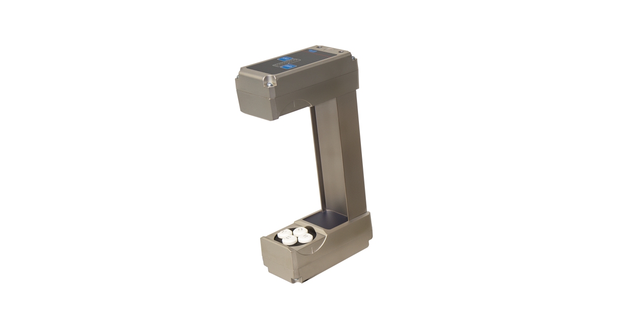
Depending on the available space, steering rollers can be equipped for web guiding with one positioning roller (web is guided with a 90° wrap) or two positioning rollers (lower wrap angles possible). The following applies when installing an ELROLLER for web guiding: The infeed path should be the equivalent of two to three times the web width, the outfeed path should be between 50 % and 100 % of the web width. The sensor should be positioned behind the positioning roller, as near to it as possible. This offers a short response time, creating improved actuating dynamics.
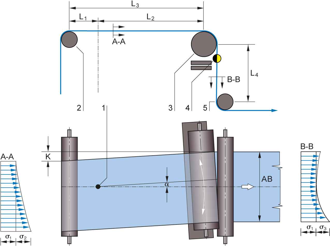
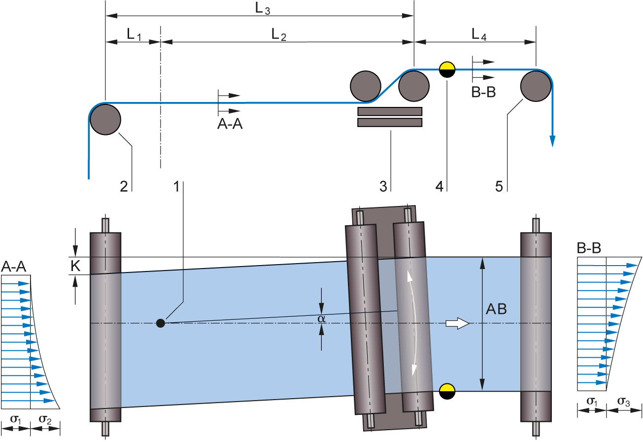
Legend

A = Web tension distribution at infeed | B = Web tension distribution at outfeed | K = Correction of the web guiding | a = Correction angle | σ1 = Basic web tension | σ2 = Tension distribution through swing movement of the roller frame at the infeed | σ3 = Tension distribution through swing movement of the roller frame at the outfeed | 1 = Pivot point | 2 = Infeed roller | 3 = Positioning roller(s) | 4 = Sensor | 5 = Fixing roller | L1 = Infeed path to the pivot point | L2 = Infeed path from the pivot point to the steering roller | L3 = Infeed path | L4 = Exit path

Web guiding systems

Schiebewalzensystem ELROLLER SRB43

Kompaktes Schiebewalzensystem für Nennbreiten von 400 bis 2400 mm und eine maximale Bahnkraft von 700 N

More info

Schiebewalzensystem ELROLLER SRB53

Kompaktes Schiebewalzensystem für Nennbreiten von 1100 bis 4000 mm und eine maximale Bahnkraft von 2000 N

More info

Schiebewalzensystem mit 3 Walzen SRB63

Kompaktes Schiebewalzensystem mit drei Walzen für Omega-Umschlingung und eine maximale Bahnkraft von 20.000 N

More info

System components

Infrarot-Kantensensor PoE FR 54

Infrarot-Kantensensor nach Prinzip der Retroreflexion mit einem Messbereich von ±10 mm und einer Auflösung von 0,02 mm

More info

Ultraschall-Kantensensor PoE FX 42

Ultraschall-Kantensensor mit digitaler Auswertung, Sichtbereich von ±3 mm und Gabelweiten von 30, 60 und 124 mm

More info

Blue light-Breitbandsensor PoE FR 65

Blue-Light-Durchlichtsensor mit großem Messbereich von 160 / 320 und 480 mm

More info

Infrarot-Breitbandsensor FE 46

Digitaler Infrarot-Breitbandsensor für Bahnmitten-, Bahnkantenerfassung und Breitenmessung mit einem Röhrenabstand (Lichte Weite) von 160 mm

More info

Ultraschall-Kantensensor PoE FX 52

Ultraschall-Kantensensor mit digitaler Auswertung, Sichtbereich ±10 mm und Gabelweiten von 30, 60 und 124 mm

More info

Infrarot-Breitbandsensor FE 45

Digitaler Infrarot-Breitbandsensor für Bahnmitten-, Bahnkantenerfassung und Breitenmessung mit einem Röhrenabstand (Lichte Weite) von 80 mm

More info

Infrarot-Breitbandsensor PoE FR 61

Infrarot-Breitbandsensor mit großem Messbereich von 160 mm, 320 mm oder 480 mm

More info

Bediengerät DO 42

Visualisierung und Bedienung von Bahnlaufregelsystemen mit Mehrfachbedienung von bis zu 255 Bahnlaufregelkreisen

More info

Daten-Netzwerkzentrale DN 40

Daten-Netzwerkzentrale zum zentralen Anschluss aller Komponenten in einem Regelsystem

More info

Stellsupport VS 80

Motorisch lineare Sensorpositionierung für Ultraschall-, Infrarot- und Farbliniensensoren

More info

Contact

Write to us! We are looking forward to your message.

Salutation
*Required field