
- Description
- Function drawing
Function
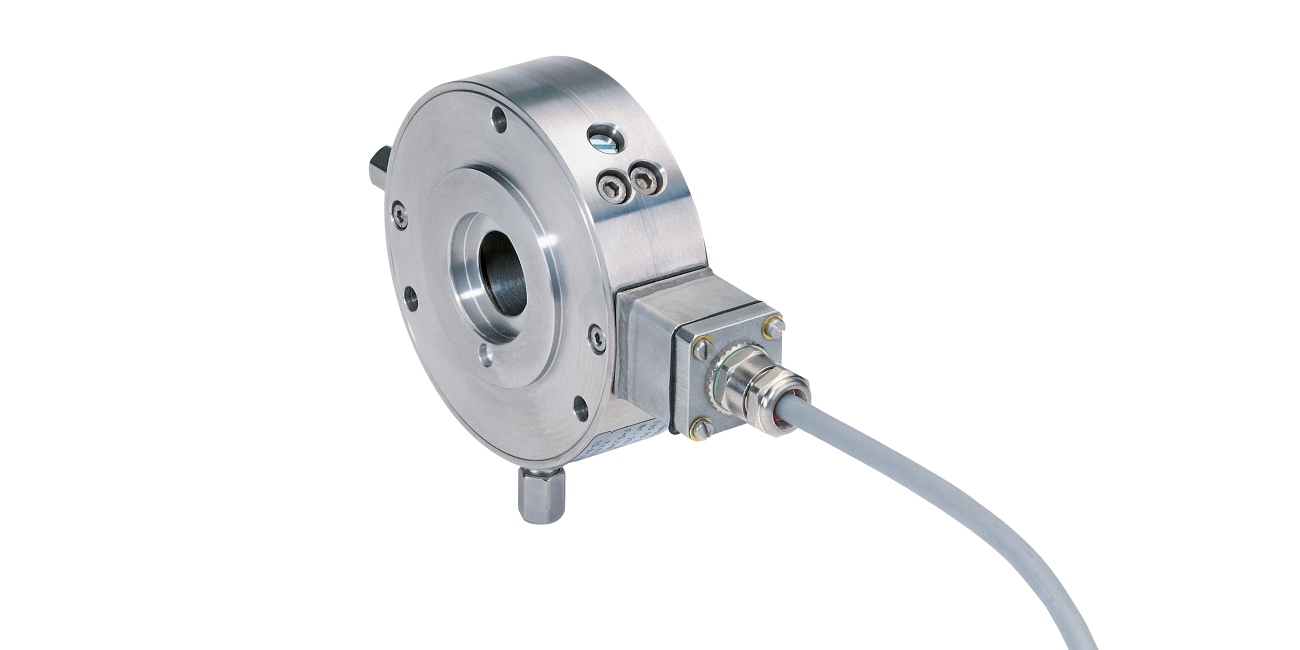
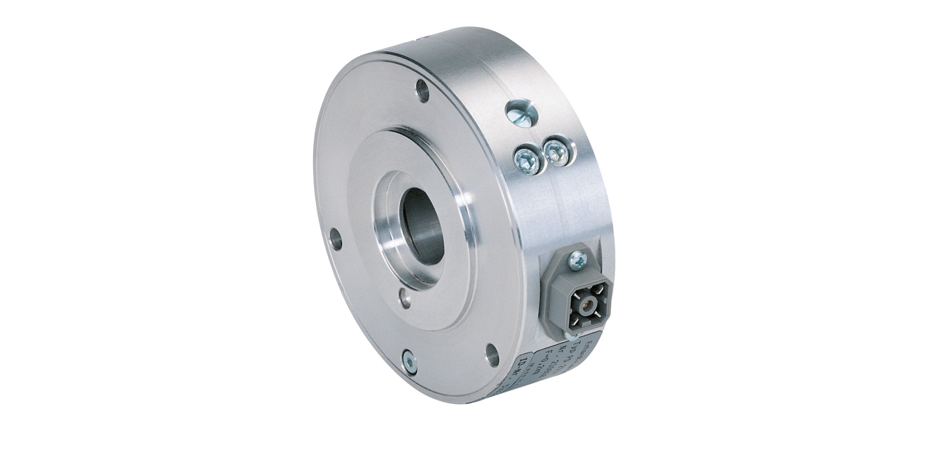
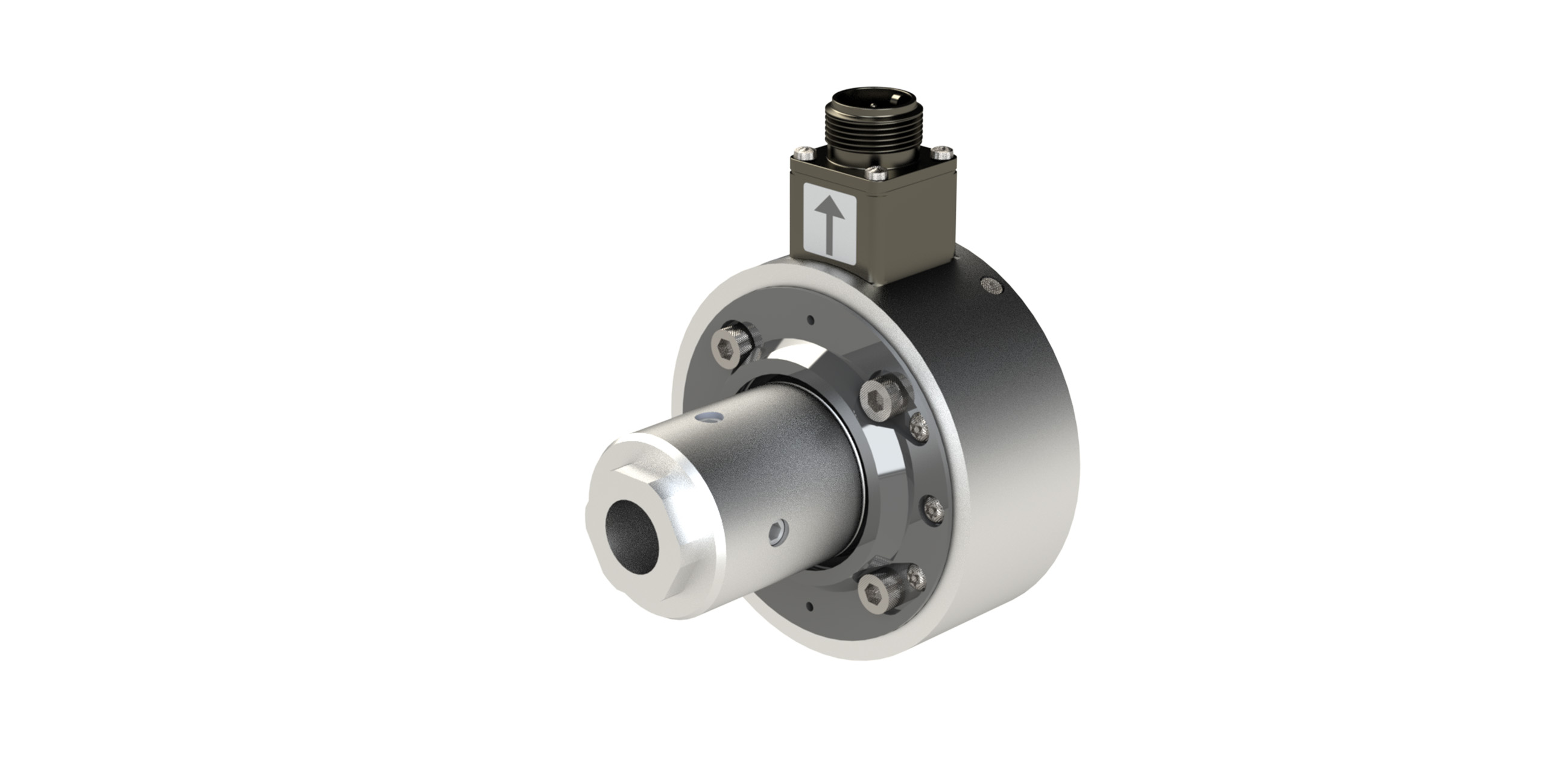
The load cell comprises a stable outer ring with flange cover and centering collar for precision assembly. The inner ring in the form of a double bending beam ensures centered mounting of the ball bearing. The radial forces created by the web unbalance the strain gauges linked together to form a measuring bridge on the inner ring. This leads to an analog output signal proportional to the web tension.
Area of use
Flange load cells are used in practically all production plants where web-type materials are processed or finished. In front of processing stations, in particular, it is of fundamental importance that the web is transported with a continuous web tension.
Application
With a 90° horizontal-vertical wrapping angle on the measuring roller and a horizontal measuring direction, optimal acquisition of the web tension is assured. Only the double-sided acquisition of the resulting force on the left and right FR/K prevents incorrect measurements caused by lateral web movement and asymmetrical web tension distribution. Load cells incorporated into a closed control loop are to be mounted as near as possible to the actuator.
Calibration
The tensile force-path characteristic curve forms a straight line to the mechanical stop. All the load cells with the exception of the PD 25 series are calibrated to the nominal measuring force. Between the nominal measuring force and mechanical stop, a safety factor of 50 to 100 percent is taken into account to compensate for asymmetrical web tension distribution.

Legend
F = Web tension (N) | F1 = Force component 1 in measuring direction (N) | F2 = Force component 2 in measuring direction (N) | FG = Weight force (N) | FR = Resulting force in measuring direction (N) | FR/K = Resulting force/load cell (N) | α = Angle between departing web and measuring direction | β = Angle between incoming web and measuring direction
Calculation, flange load cells
Calculation, sensor rollers
F1 = F x cos α
F2 = F x cos β
FR/K = (F1 + F2)/2
F1 = F x cos α
F2 = F x cos β
FR = (F1 + F2)
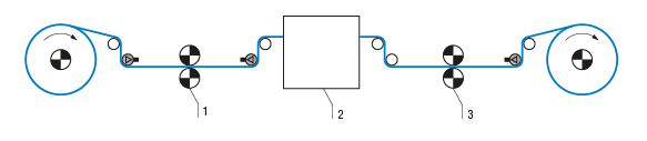
Legend
1 = Transport drive | 2 = Process | 3 = Main drive
Characteristic curve
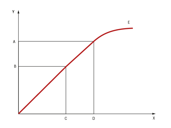
Legend
Y = S (mm) | X = F (N) | A = S Stop | B = S Nominal | C = F Nominal | D = F Stop | E = s = f (F)
NEW: Configure your own web tension measuring and control system

Customize - visualize - realize
With the MY E+L configurator, you can easily configure your load cell and watch your ideas become reality! To be able to configure a product, you need an active MY E+L account. Log in or register here. You can then start with your configuration.
Looking for more details on the E+L Configurator? Discover all features here.
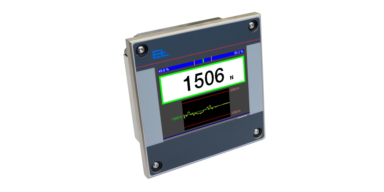
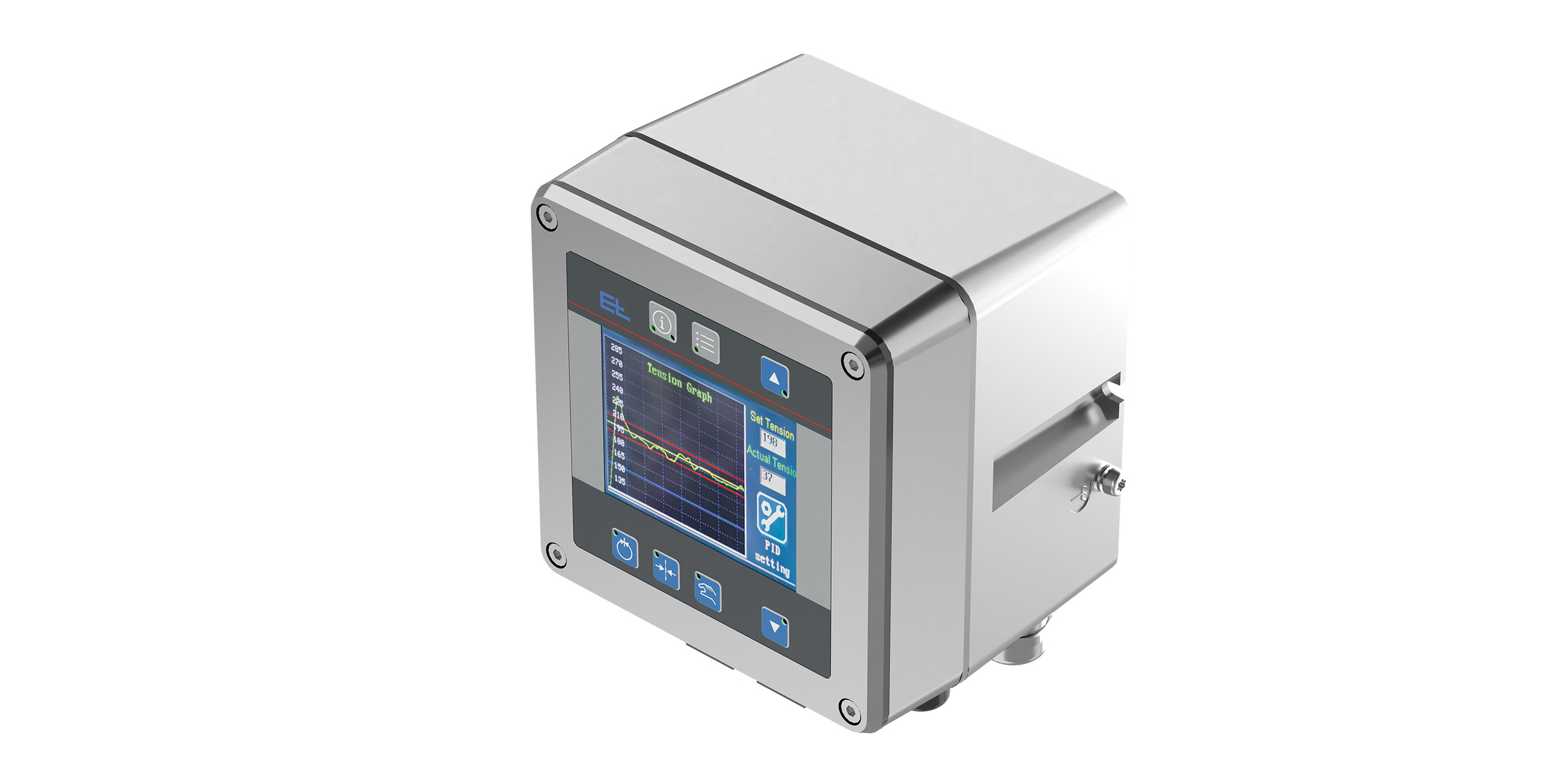
ELTENS web tension measuring and control system
Product types: PD 21, PD 22, PD 23, PD 24, PD 25, PD 26
- Individual configuration with customizable load cells and accessories for various industrial applications
- Choice between analog and digital measuring amplifiers, installation options in control cabinet, control panel or directly on the machine
- Connection to customer controls via analog signals or Ethernet interfaces with various protocols.
Advantages of the E+L Configurator