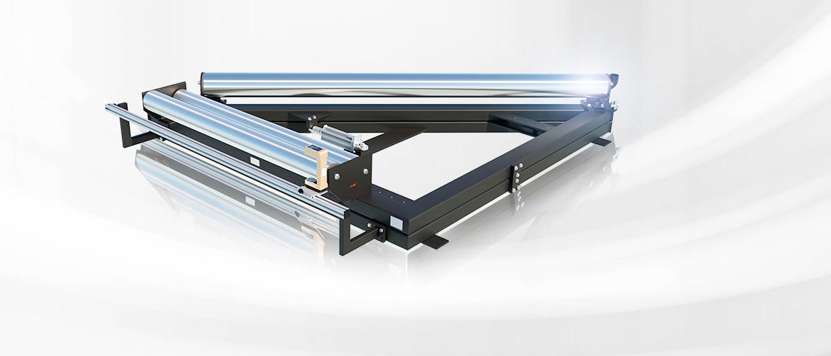
- Description
- Function drawing
Function
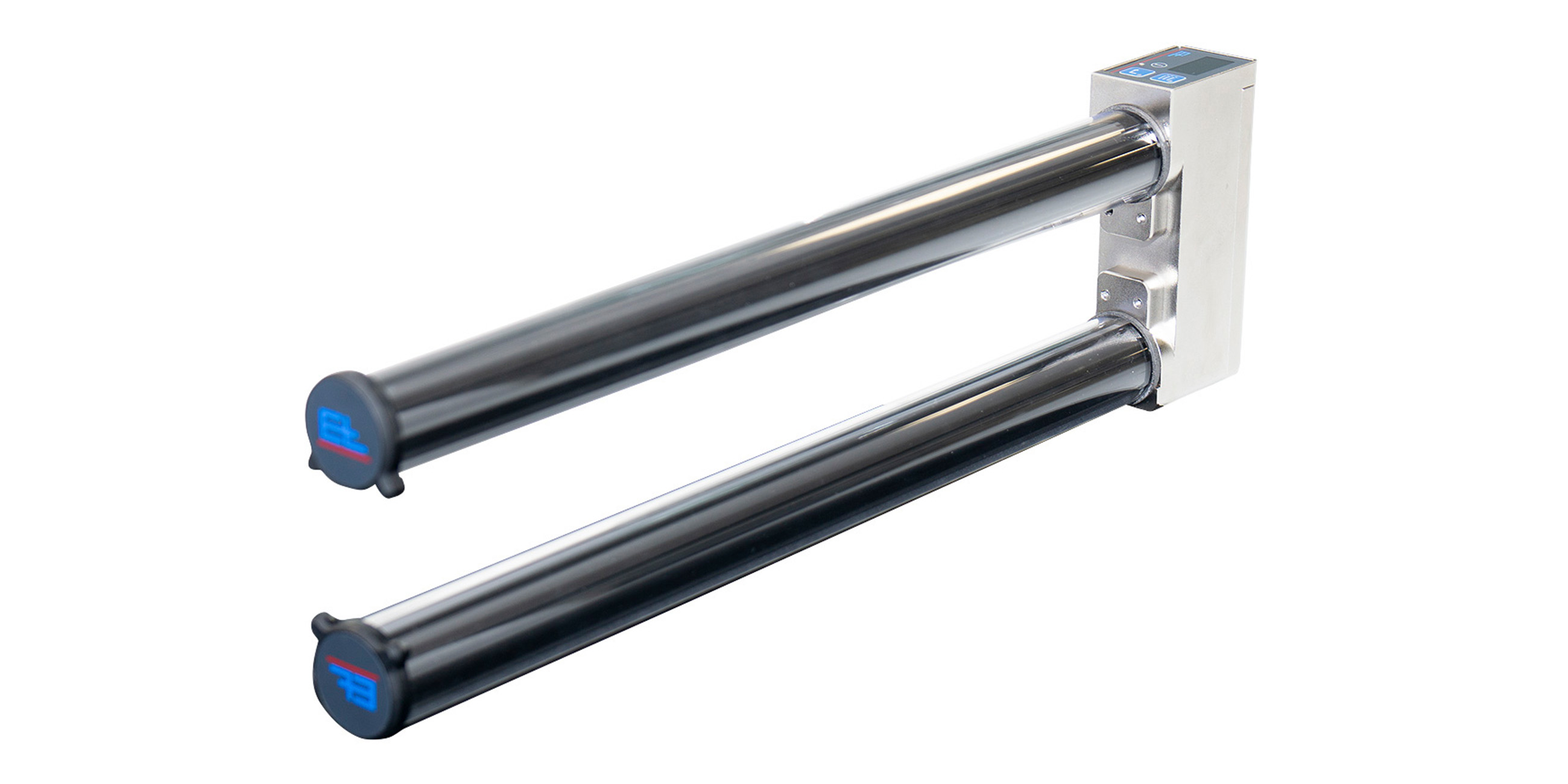
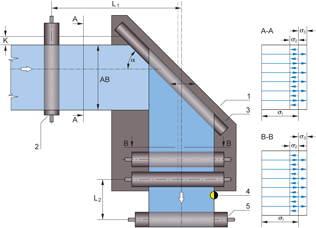
Web guiding with ELTURNER turning bar systems is based on a simple principle: A bar is mounted at an angle of 45° to the longitudinal and transverse axes while the web runs over it with 180° wrapping. This has the immediate effect of changing the direction of web travel by 90°. To correct the web position at the same time, the turning bar is moved parallel to the infeed plane according to the actuating signal, thus offsetting the web to the side as it runs off.
Area of use
Use of a turning bar control system for web guiding is recommended in cases where space restrictions prevent the use of an ELGUIDER or ELROLLER system after the 90° deflection.
Application
When the turning bar is used for web guiding, there must be points of traction between the bar and the web. To protect the web surface, the friction can be reduced by inserting an air cushion between the turning bar and the web. Positional accuracy of up to ±1 mm can be achieved. For improved adjustment dynamics, a guide roller should also be moved together with the turning bar. The distance between the guide roller and the locking roller should correspond to half the web width. The sensor should be mounted immediately after the outfeed roller as close as possible.
Legend
A = Web tension distribution at infeed | B = Web tension distribution at outfeed | K = Correction of the web guiding | a = Correction angle | σ1 = Basic web tension | σ2 = Tension distribution through actuating movement to left | σ3 = Tension distribution through actuating movement to right | 1 = Guide frame | 2 = Infeed roller | 3 = Turning bar | 4 = Sensor | 5 = Fixing roller | 6 = Pivot point | LÜ = Transfer length | L1 = Infeed path | L2 = Outfeed path | AB = Operating width