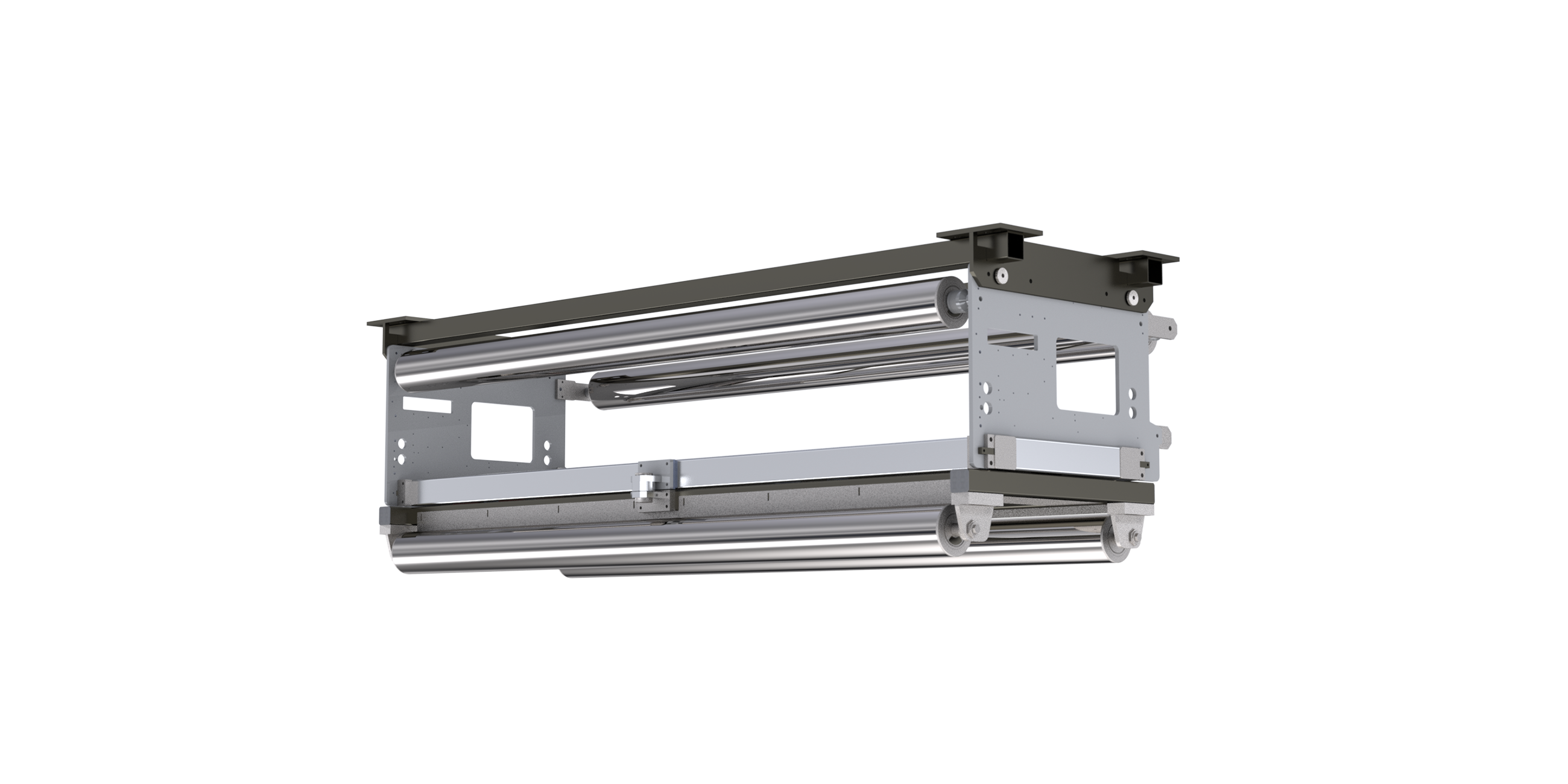
- Description
- Function drawing
Function
On a pivoting frame system, the web changes direction four times, each time by 90°. This web guiding system is based on a pivoting frame with two path rollers. The imaginary pivot point is located on the infeed plane. Lateral web corrections can only be achieved by pivoting around this pivot point. The prerequisite here is that there must always be sufficient web tension for friction-locking between the web and the positioning roller.
Area of use
Thanks to optimized exploitation of elasticity ranges, the pivoting frame can be used for web guiding even in really tight spaces.
Application
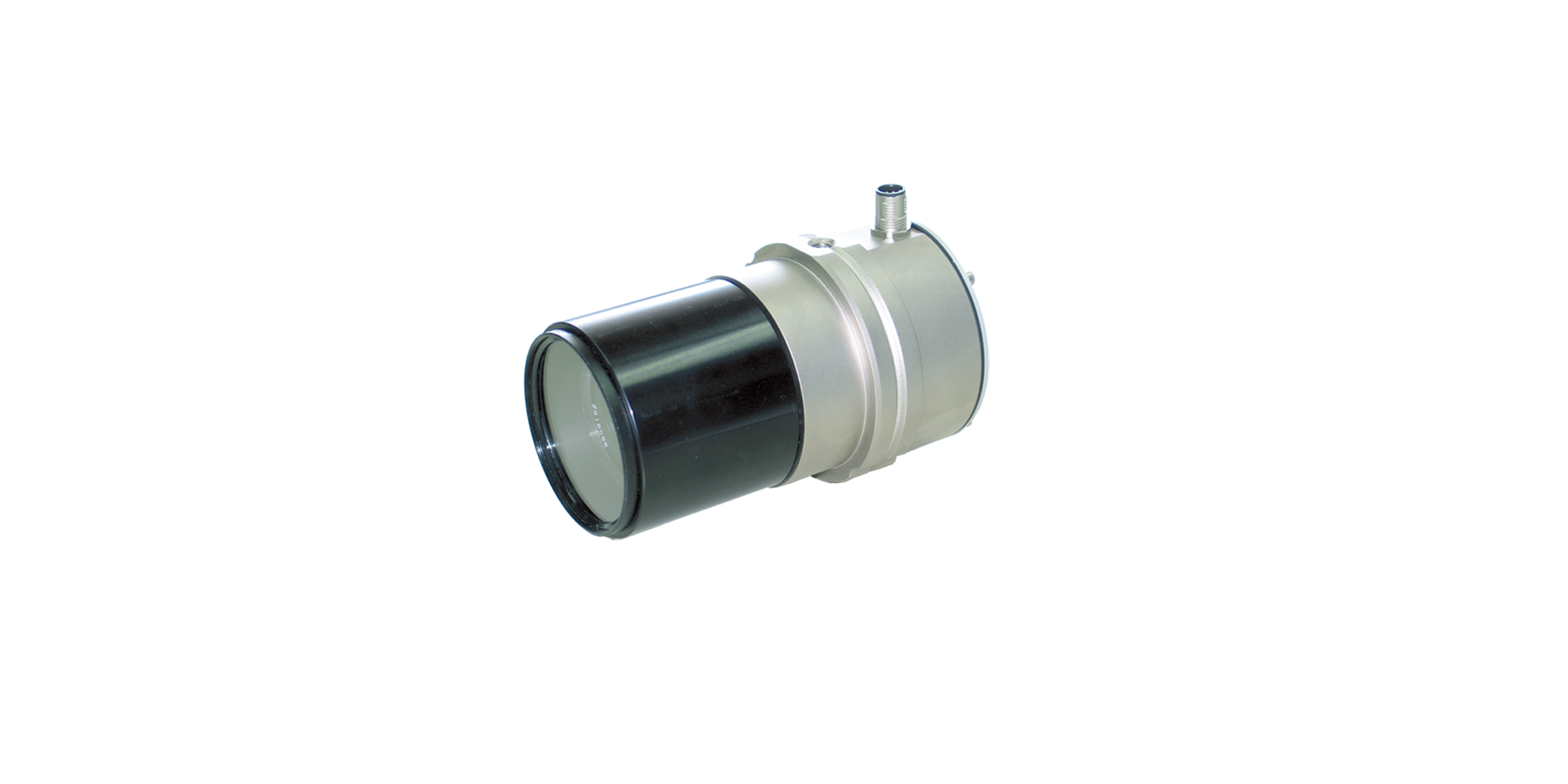
The greater the web tension, the modulus of elasticity and the required correction, the longer the infeed, exit and transfer paths should be designed. Experience has shown that the length of these paths should be the 60 - 100 % of the web width. The sensor should be positioned behind the positioning roller, as near to it as possible.
Legend
A = Web tension distribution at infeed | B = Web tension distribution at outfeed | K = Correction angle max. ±5° | σ1 = Basic web tension | σ2 = Tension distribution through swing movement of the roller frame at the infeed | σ3 = Tension distribution through swing movement of the roller frame at the outfeed | 1 = Pivot point | 2 = Infeed roller | 3 = Roller frame | 4 = Sensor | 5 = Fixing roller | LÜ = Transfer length | L1 = Infeed path | L2 = Outfeed path | AB = Operating width


